It's no problem sharing my OX cnc build experience, I'v been meaning to do this for a while to help out others making the dive into a cnc router. So I guess I'll start with one of the most important parts of the build, which is an extremely sturdy base. It may seem like overkill, but it provides a vibration free operation. 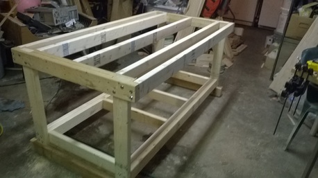
Here is another view of it with two layers of 3/4" MDF for the top. 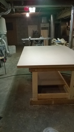
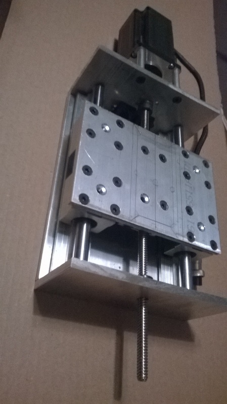
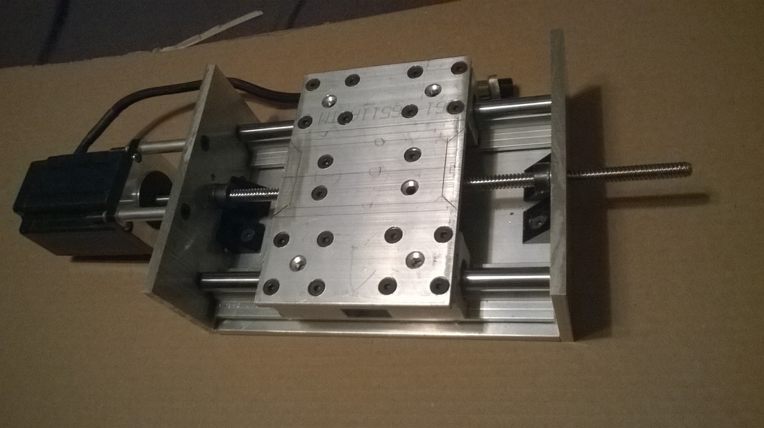
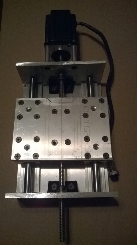
This section of photos contains my Z axis build, which for the OX cnc router in my opinion is a must. When I had the original Z axis from the OX build it had way to much deflection even for a fair amount of hardwoods. The Z axis is made up from 6061 aluminum plate, the motor is a NEMA 24, (420 oz) which provides plenty of torque for just about any operation (All of the motors on my OX build are NEMA 24 motors, from Automation Technologies, it was a four axis kit, which came with - 4 motors, 4 steppers, a 36v power supply, and a break out board). The linear rails were picked up on Ebay, and they are SBR12 supported rails, that came with the 4 pillow block bearings. They are 200mm long. Again the reason I'm sharing this Z axis build is because this type of linear carriage provides the rigidity needed for milling hard materials. 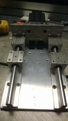
(Below) - View of the back of the plate which is drilled for matching up with the original Y axis back plate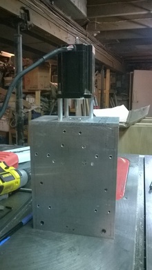
View of delrin acme nut that mounts into the end of the aluminum extrusion, and while I'm at this point I'd like to point out that this delrin nut does serve the purpose for most applications. But it does begin to get some slop after some use, with that being said I'll be upgrading to an anti-backlash nut. To make sure I provide all the infomation I can, the TR8*8 lead screw from OpenBuilds is difficult to find an anti-backlash nut for. They are out there, but they are difficult to find, so when I do end up changing to an anti-backlash nut, I will be going the route to change out the lead screw completely to something more common, and that comes with an anti-backlash. But for now the delrin nut will suffice. 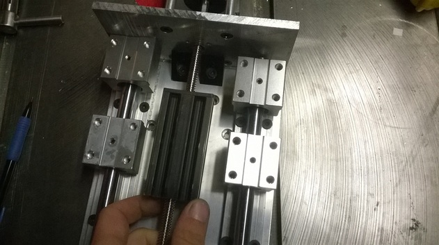
I should note that the holes in the center of the five bolt patterns of the pillow blocks, are drilled out, because there is an adjusting set screw in the center to take out any slop that may be there, for smooth no play travel. 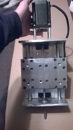
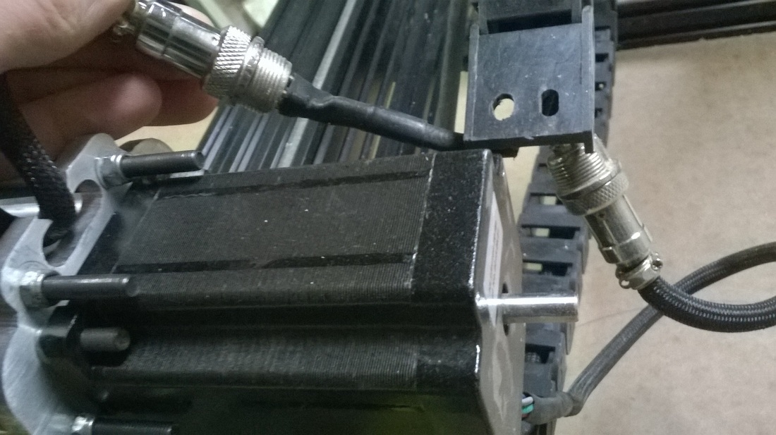
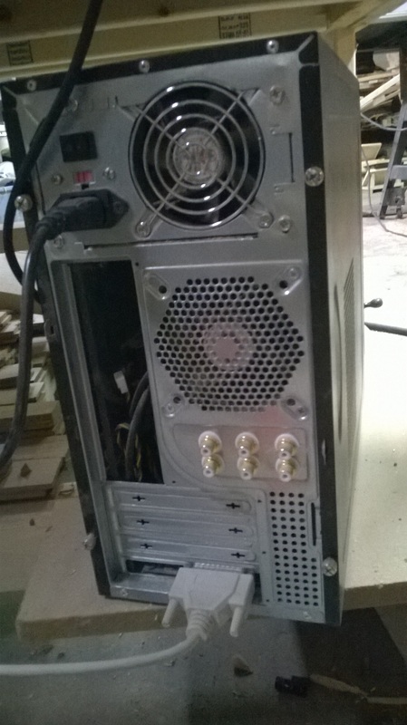
The last three pictures in this section are of the completed carriage. This section below are pictures of the connectors and the electronics I used in this build. As you can see below, I used avation connectors, the reason I went this way is so if i ever had to relocate my machine all the electronics would be easily plug and play. Keep in mind if you go this route you will have to solder all connections, it will be time comsuming, but worth it in the long run. To add one more thing on the subject, make sure to keep a multi-meter handy so once you get all your connections soldered you can test for continuity, which is vital, because once everything is soldered and together the last thing you want to happen is to have a bad electrical connection that you have to find. This below is a cheap PC Tower box that I bought to house all of the electronics. In this picture you can see the plug and play at work, with the aviation connectors. Also one of the most important and must have things with a CNC is an Emergency-Stop button. I fabricated the front panels on the tower to house the Connectors, and the E-stop, for ease of access. 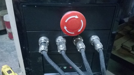
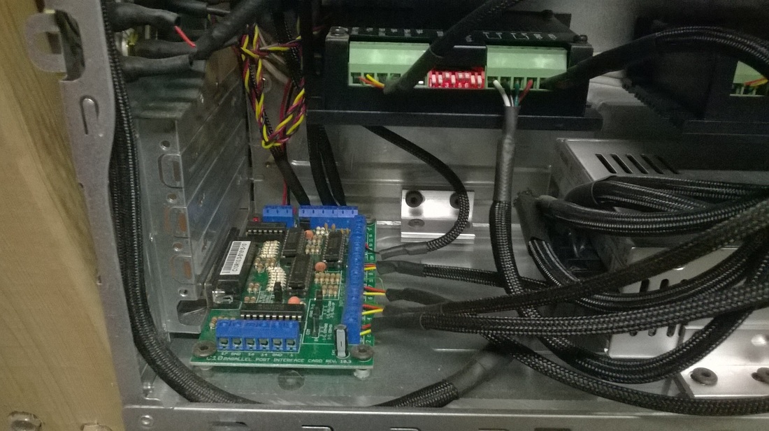
This is a view of the E-Stop and Connectors from inside the tower. (below) I also wanted to add if you haven't noticed, I sleeved all of the wires in expanding nylon sleeving from McMaster-Carr. I also used heat shrink tubing to get a clean tight finished look and operation of all the connections. The reason for the sleeving is to better protect the wiring from anything that may or may not occur. (It is completely optional) 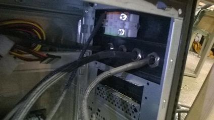
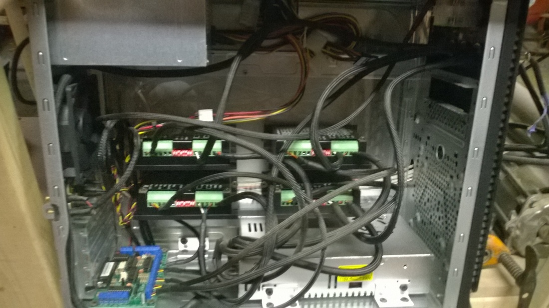
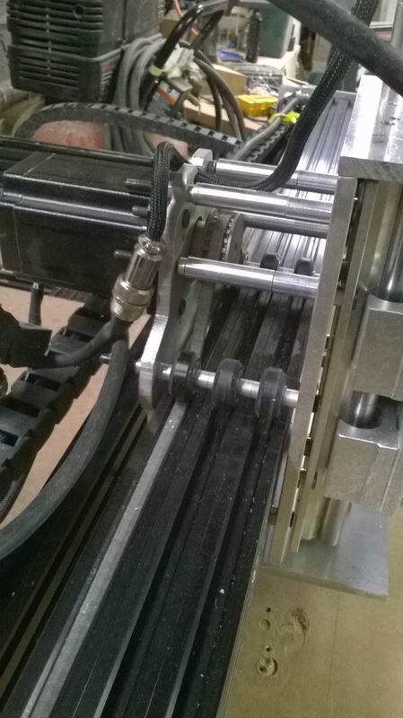
In the next picture you can see all of the components arranged inside the tower. The tower has 2 power supplies that are wired in series, so one power button operates all the power to the box. Another reason for wiring them both together is so i could use the smaller PS for the lower voltage operations since it's already prewired for 12v, and 5v, which was used for the BOB, E-stop, and an extra fan that I mounted in the back of the case. Also a view of the back of the tower showing the single power switch, the gold plated connectors for the limit switches, and the parallel port plug. The pictures below all go hand in hand with the major reason of this post (rigidity). As you can see here instead of going with two stacked rails for the Y axis, I stacked three peices of 20x60 extrusion, and bolt them together so they are stacked tight as if they were all one solid piece of extrusion, if done with out bolting them together, no real strength is gained, because everything wants to flex independently of one another. I added a third extrusion in part because of the new heavier Z axis which this has to support, and to try and create a wider footprint with three solid v wheels wide, to try and get better leverage and avoid the flex that lateral cutting forces have. I should note that it did help a lot, but I will still be upgrading this later, to SBR, THK, or Hiwin linear guides. Nothing can beat the strength and rigidity of those. The way the setup is now, cutting aluminum is slow, and has a small amount of chatter from the lateral flex. 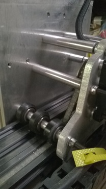
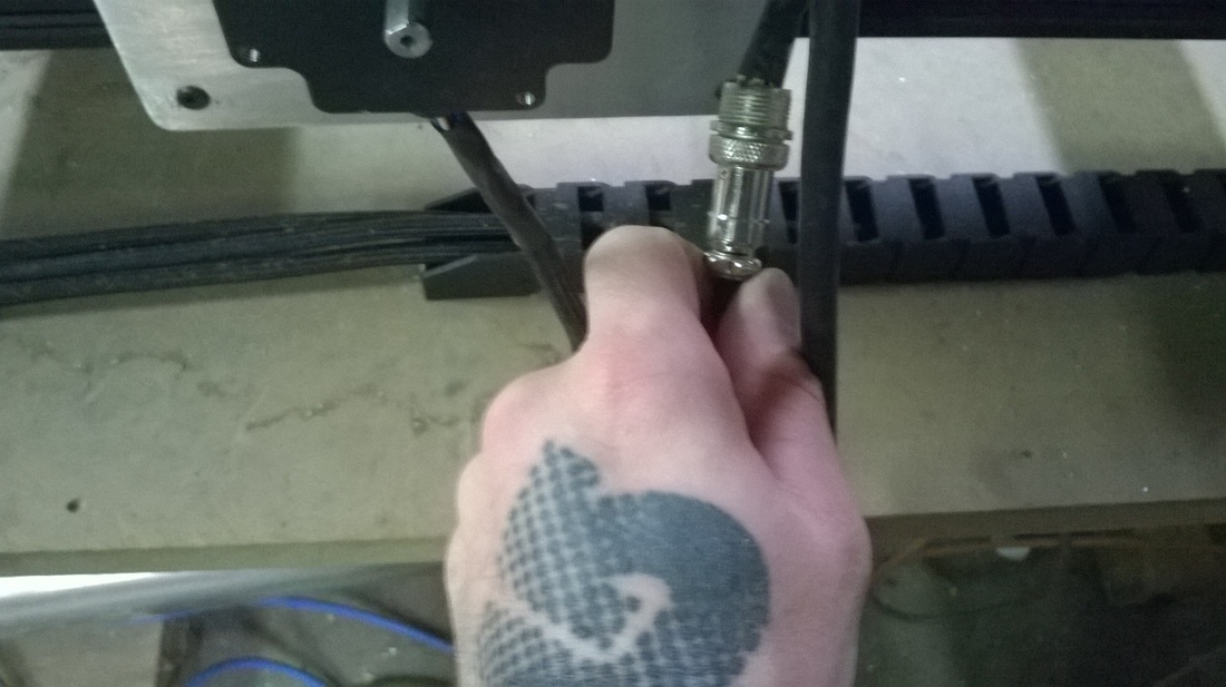
In this picture you can see me pointing toward the bit, this is because this is where all your strength needs to be when cutting aluminum, even with a good speeds and feeds calculator, and cutting at the optium speed, and feed ratio it still barely gets by. There is chatter, in a way where you'd have to spend a small amount of time cleaning up your aluminum parts, and definately if you were planning on milling aluminum for jobs. Another thing to mention is I was cutting with 2 flute coated carbide endmill, specificly engineered to mill aluminum effectively. Again this is no discouragement, or insulte to the OX cnc, this is purely referance infomation for people who want to know what the aluminum cutting capabilities of the machine are. 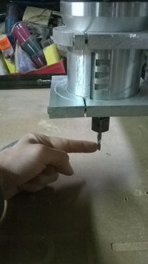
I also wanted to mention on another topic of strength and torque needed for aluminum milling, are good quality pulleys. You can see the original aluminum pulley's next to the upgraded steel pulley from McMaster-Carr. This was another turning point in this machine, the new pulleys have deeper teeth and the belt has also has deeper teeth which creates a much more positive grip with one another. 
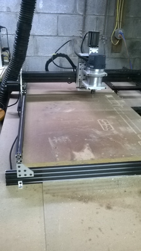
This is an overall view of the cnc, and the entire setup. (Note Air compressor right next to the cnc, chip clearing is top priority when milling aluminum, if you don't clear chips two thing can occur, one they can get to hot along with the cutter and weld themselves to the cutter and back to the aluminum. The second thing being you will pre-maturely dull your expensive endmill, because you will be re-cutting the same chips. 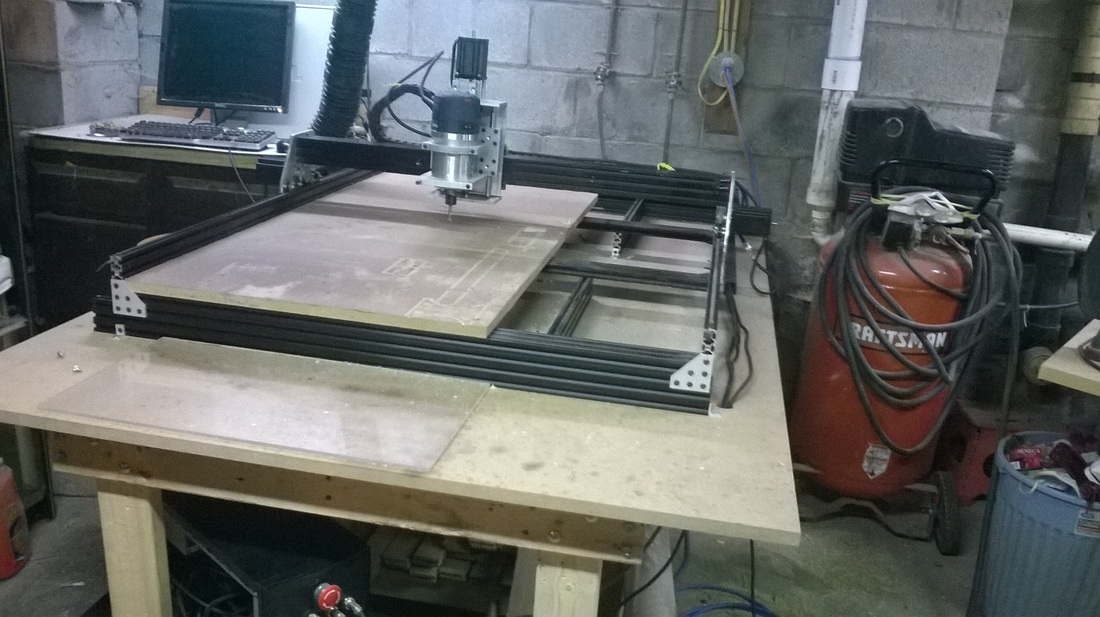
Something else I wanted to note, is when using this belt system and cutting harder materials like aluminum, you will have to check and re-check your belt tension, because they will come loose due to the torque and strain during cutting. A wiser move, which I think I have seen somewhere here on OpenBuilds site, would be to create a belt tensioner, that clamps the belt tighly so it can not creep. This way you can rest assured the belt will stay tensioned properly through out your cutting. 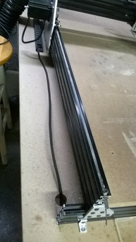
(Below) This is an upclose shot of the Back Plate of the Y axis carriage. The reason I'm showing this is I utilized the extra holes that were in it's design. Using these extra spots for spacers allows the Y carriage to have way more rigidty, it is the way shapeoko desktop cnc's are assembled. 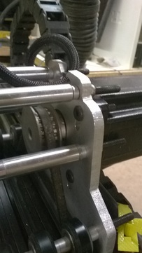
Now onto the structure/body of the cnc. Here you can see I have created a bed of extrusions spanning the entire 1500mm length of the x axis. This is nice, but i really applied those extrusions so I could add the next layer of extrusion across it. What that does is add strength and rigidity to the long span of the x axis rails. All of the cross peices are cross cut with a stop block to ensure each one is exactly the same length, this keeps the X axis rails completely parallel to one another. Which is extremely important to keep from any racking that could possibly occur. 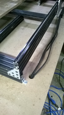
This below is a picture which was noted earlier, showing the Y axis extrusions bolted together. It was drilled to thru two of the extrusions, and halfway thru the third. Then was tapped by hand to pull everthing together, and to keep a low profile and having complications of a bolt head or a nut on the other side, which could potentially get in the way of the Y axis carriage. 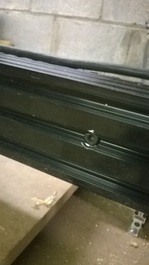
I might as well note this here, the picture below shows my router mount, and my router. I should note that I'm not using any type of VFD Spindle. This is a Bosch 1617EVS, it has a speed range of 8000rpm to I think 28-30,000 rpm. Anyway even tho aluminum is suppose to be cut at slow RPM's, with a good feed and speeds calculator, it will help account for the speed ranges covered in a basic varible speed router. 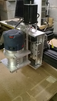
(Below) Another Picture showing the use of the spacers/standoffs, and a last pictures of the cnc. Some final words of advice for those wanting their OX cnc router to mill aluminum. My current setup does mill aluminum, but the surface finish is not purpose built mill quality, due to lack of rigidity. Also it is very slow going, my most recent aluminum milling was 1/2" thick aluminum plate. My Depth Of Cut (DOC) was .0313", or 1/32", I set my router to 12,000RPM, and the router is 2.25 HP, adding in the geometry of the cutter, Your feeds, and speeds calculator will come up with a speed for Inches Per Minute (IPM). With all those input for mine, the recommended IPM for those parameters were 10.54, which is quite slow. I'd also like to inform you that when your using Feeds and Speeds calculators, they are for professional cnc routers and milling machines. What does this mean for DIY cnc'ers, this means that you must De-Rate your machine. Those calculators are set-up to provide accurate cutting parameters for 1000lb cnc's, not a 150-200lb diy cnc. So it's best to use a calculator that also has a max feedrate setting. (Note your max feedrate rate setting should be down played from your IPM speed when cutting softer materials like wood).
To wrap this up in a final paragraph, I'm going to say what I still plan on changing, and that is the linear motion for the Y axis. As stated above, I will be switching to SBR, THK, or Hiwin rails. More than likely it will be SBR rails, because they are the least expensive of the three. (In changing this axis it should provide extremly good aluminum milling results with being able to more than likely decrease your milling time). On that note there will be some fabricating to be done when the switch occurs such as I will be using a leadscrew drive instead of belt and pulley, purely because it will be more of hassle to make a belt and pulley system work with that type of linear rail set-up. I hope this helps everyone who has or is planning to build a cnc, I'm not holding back any punches here and laying down the facts of a lightweight cnc router build, and what it really takes to mill aluminum successfully and accuatrely. Any feedback or questions about my exerience with my cnc, feel free to post or ask. :)
0 Comments
|
 RSS Feed